TTI Inc. has sponsored this post.
Batteries may be the heart of modern electric systems, but it is the Battery Management System (BMS) that keeps them operating safely and efficiently. At its core, a BMS balances voltage across cells, regulates the flow of current, and monitors temperature. When any of these values move outside safe limits, the BMS disconnects the load from the source.
“A BMS protects both the battery and the load in a system,” says Mohammad Mohiuddin, design engineer at electrical components manufacturer Eaton.
This article examines the importance of BMS technology, its main building blocks and topologies, and the tools that Eaton provides to engineers designing these systems.
Why battery systems need a BMS
Any system that relies on a battery — whether it serves as the sole power source or provides auxiliary power, and whether the battery is rechargeable or not — must be aware of the battery’s status.
“BMS is a crucial component of any system using batteries,” says Mohiuddin. “It monitors, controls, and communicates the status of the batteries to the central computer. It is a supervisory component of the power source.”
Without proper monitoring and control, the battery can be damaged beyond repair, and the load can also be at risk. “Imagine an electric vehicle without a BMS,” explains Mohiuddin. “The operator of the EV would need to have knowledge of the battery capacity along with other information about the vehicle. For example, the range of the vehicle — how far will it travel before needing to recharge? This information becomes more important as the battery ages and the capacity of the battery decreases. During operation, information such as battery temperature or the buildup of hazardous gases in the battery compartment is critical. BMS monitors and keeps the operation in safe zones.”
The same safeguards apply to life-supporting medical equipment, where a faulty BMS could prevent a backup battery from working in an emergency. In energy harvesting systems, a BMS works with batteries and supercapacitors to act as a buffer against power fluctuations and gives operators time to shut down or switch to a backup source.
Primary building blocks of a BMS
A BMS is built from several interconnected subsystems: battery monitoring, state estimation, balancing, thermal management, protection and communication.
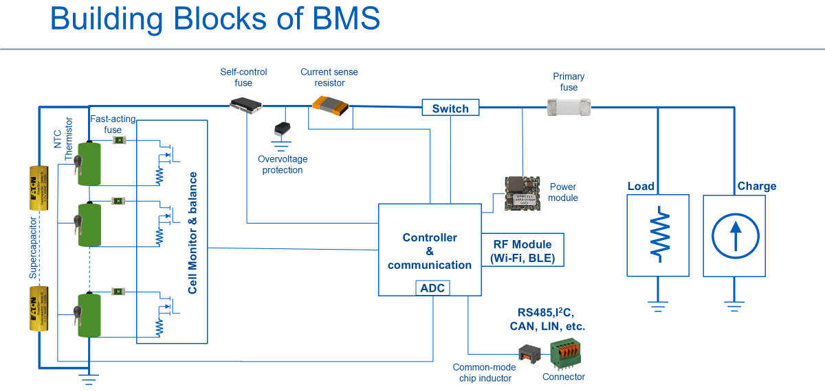
Battery monitoring
As discussed earlier, battery monitoring involves measuring the voltage, current and temperature of individual cells or a group of cells within the battery pack.
State estimation
This includes algorithms that estimate key battery conditions. These metrics help predict the remaining capacity and overall health of the battery.
State of Health (SoH) measures overall battery capacity in percentage amp-hours (%Ah), factoring in age, cycle count and temperature history.
State of Charge (SoC) reflects how much usable capacity remains since the last full or partial charge.
A common method to estimate state of charge is Coulomb Counting:
SoC Present (%)= SoC Initial (%) – Capacity Utilized (%), where
Where:
- I = Current (Amperes)
- Δt = Time interval
- Initial Capacity (Ah) = Rated capacity of the battery
State of Energy (SoE) is the remaining energy in the battery vs the maximum energy a battery can store.
Energy Change (ΔE):
- ΔE = P x Δt
- Where P = V x I
- Therefore Δ E = V x I x Δt
State of Energy (SoE):
- E Present = E Max – ΔE OR
State of Power (SoP) comes from the relationship between voltage and current, while State of Energy compares remaining energy to the battery’s maximum capacity. As stated earlier, Power (P) is the product of Voltage (V) and current (I).

Balancing
Balancing ensures that all cells within a battery pack charge and discharge evenly. The BMS accomplishes this through passive balancing, which dissipates excess energy as heat, or active balancing, which redistributes energy among cells to maintain uniform charge levels..
Thermal management
Managing the battery pack’s temperature is critical for safety and performance. The BMS monitors and controls the cooling and heating systems to maintain optimal temperature ranges.
Protection
A BMS protects against potentially damaging conditions such as overvoltage, undervoltage, overcurrent, short circuits and overheating.
Communication
The BMS subsystem interfaces with other systems — such as a vehicle’s control unit or a renewable energy system’s inverter — using widely adopted protocols like CAN bus, UART and I2C, either through wired or wireless connections.
BMS topologies
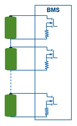
BMS topologies can range from simple to highly complex, depending on the scale of the application. The most basic topology uses a single BMS to control a small number of batteries, matching the number of cells to the available resources of a microcontroller or processor. This approach works well for compact systems such as power tools, small UPS units and laptops.
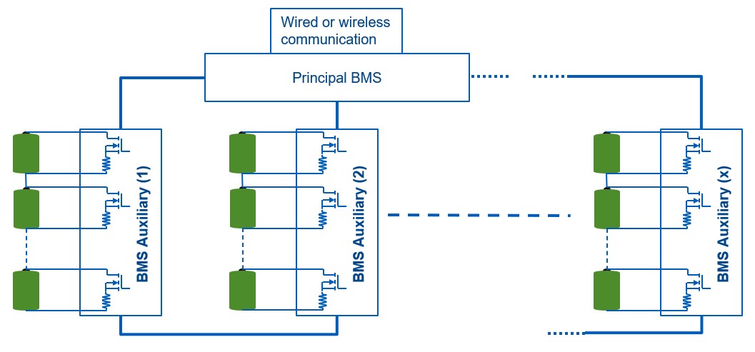
More complex systems include multiple BMS units, each overseeing several batteries and communicating with a principal BMS that relays information to the main computer. This arrangement suits applications like large UPS systems, e-bikes, and portable power stations.
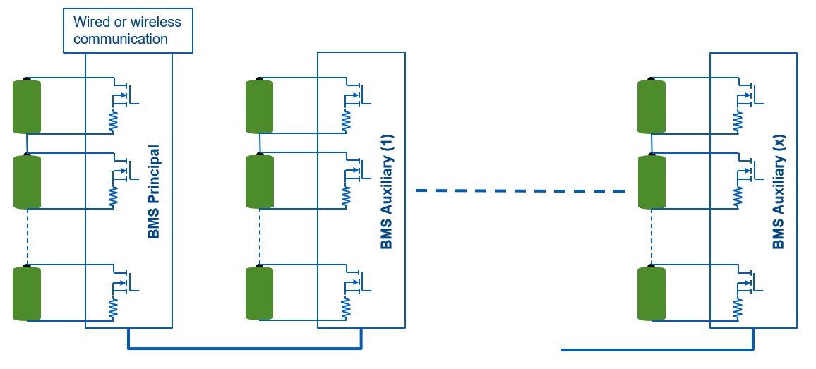
At the highest level, multiple BMS units manage even more batteries, for applications like electric vehicles, solar backups, and data centers.
Eaton’s BMS tools and expertise
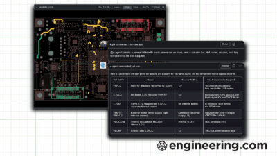
Eaton supports BMS development with a wide range of passive components, including magnetics, capacitors, circuit protection for overvoltage & overcurrent, sensors, crystal resonators, fast recovery diodes and terminal blocks. Engineers can also draw on application notes, component selection guides and whitepapers.
“It doesn’t matter where the design is being done,” says Mohiuddin. “We have live experts around the world who can help anyone designing the system.”
To learn more, visit Eaton.