Maintenance Reseller Corp. has sponsored this post.
Traditional design workflows often follow a linear path, from concept creation to prototyping and finally performance analysis. However, when the performance analysis exposes a critical flaw late in the sequence, redesign would extend production cycles and increase development costs. To avoid this, many engineers are adopting simulation-driven design, a process that integrates analysis into the workflow from the start and throughout the entire process.
“By moving analysis earlier in the workflow, engineers can design for risk mitigation, quality, and performance,” says Jerry Raether, sales training program manager at PTC. “Instead of creating a part that passes validation, simulation-driven design enables them to refine and optimize until they achieve the best possible design.”
Integrated simulation also reduces development cycles by identifying and correcting potential flaws in real-time, thereby minimizing the back-and-forth between design and analysis teams. This allows engineering companies to bring products to market faster and reduce development costs.
To support this fundamental shift, PTC has integrated analysis tools directly within the Creo 3D CAD environment. Solutions such as Creo Simulation Live and Creo Ansys Simulation eliminate the need for data export or manual setup. The workflow offers a strategic advantage for product development teams, allowing them to refine a concept in real-time based on live performance data.
In this article, we will discuss two key workflows that use simulation-driven design in PTC Creo: one for new product development and another for existing product improvement. Each of these workflows demonstrates how extensions like Generative Topology Optimization (GTO), Creo Simulation Live (CSL), Behavioral Modeling Extension (BMX), and Creo Ansys Simulation enable an integrated design-analysis process.
Workflow 1: Simulation-driven new product design
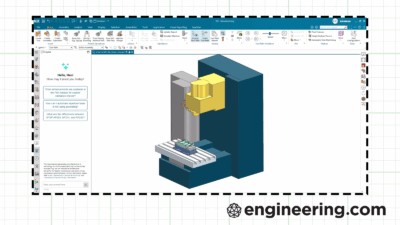
In a new product design workflow, GTO is used as a concept design tool to rapidly explore and reveal innovative design solutions. GTO is 3D CAD capability that uses AI-driven algorithms and FEA to autonomously create optimal designs solving for user specified requirements and goals, including preferred materials and manufacturing methods.
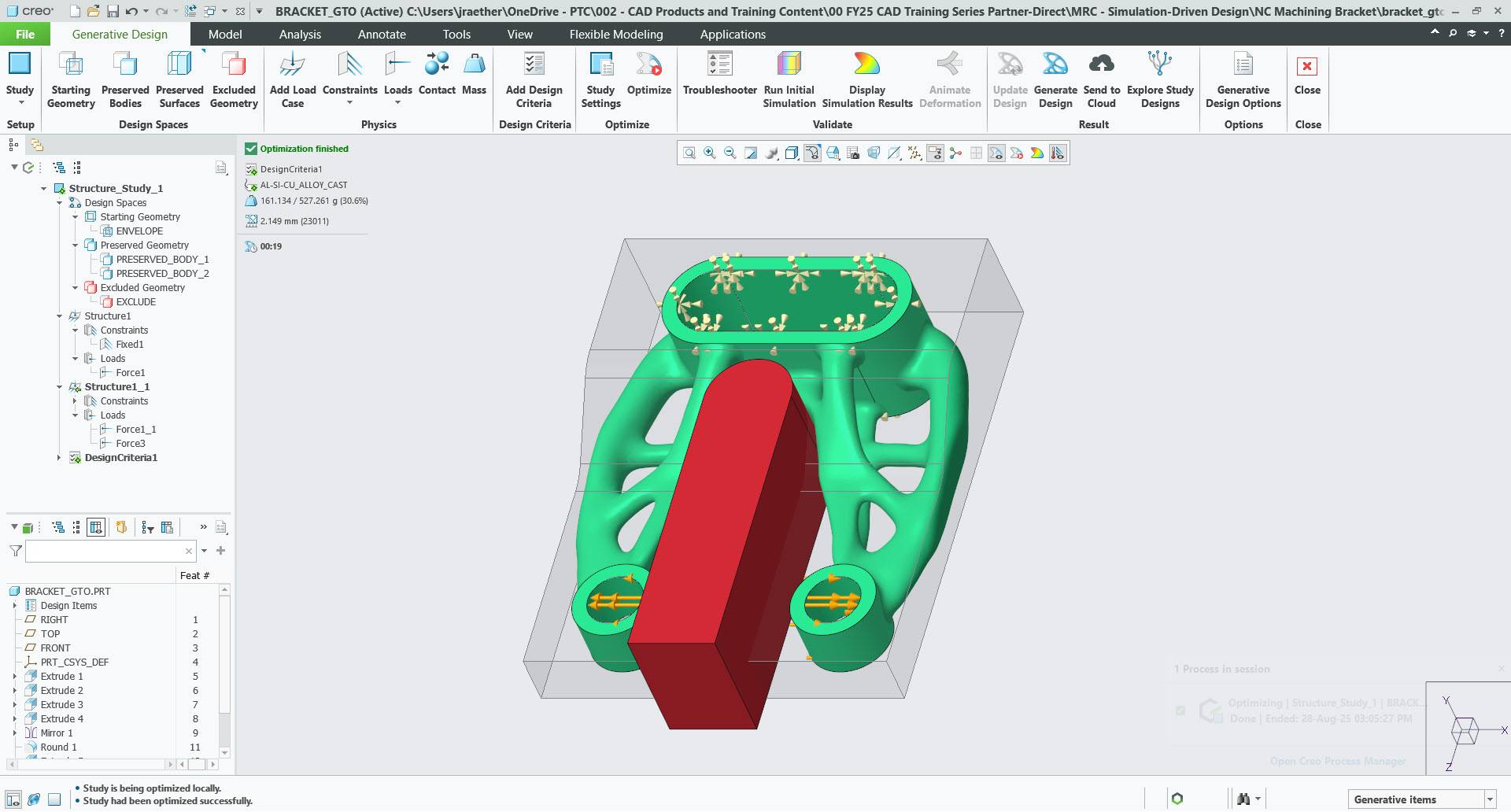
The workflow starts using Creo multibody design to create the design spaces representing the starting geometry, preserved geometry and optional exclude geometry. Once the geometry is created, the user starts the GTO application and completes the setup by designating the design spaces, defining the physics, and design criteria. The last step is to generate the design by selecting the option to optimize. The user can run as many optimizations as desired to evaluate design alternatives while changing material selection, manufacturing methods and geometric constraints.
“Using generative, I define all these criteria, and then I tell it to optimize and solve for the part. What it’s going to do is come back with a really unique-looking part that will be something an engineer wouldn’t naturally think about designing that way. It speeds time to innovation because it shows a lot of different ways to create that part that an engineer would never think of,” explains Raether.
Jacobs Engineering used PTC Creo Generative Design to design and optimize two components of the NASA spacesuit Portable Life Support System: the O2 tank bracket and the CO2 sensor bracket. The company achieved significant improvements, with a 21 percent and 20 percent weight reduction, respectively.
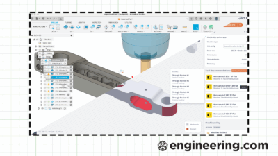
After GTO has provided the conceptual blueprint, the engineer begins the recreation phase, using traditional Creo tools such as parametric design, surfacing, and freestyle, to create a cleaner, more manufacturable version. The generative output is not a final, manufacturable product, as it may not be suitable for die-casting or NC machining.
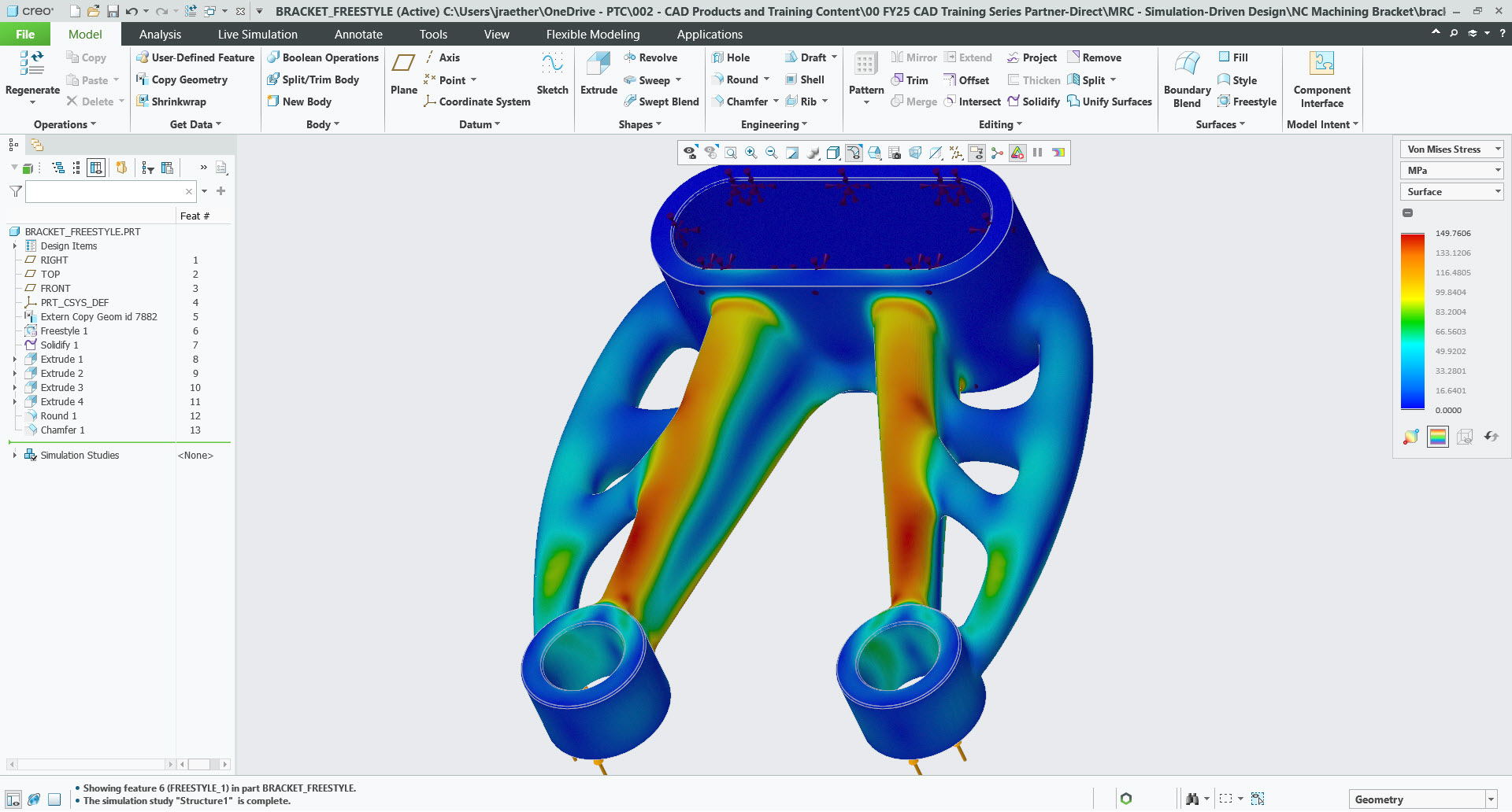
While the engineer reverse-engineers the GTO output, CSL runs in the background, providing real-time feedback on key performance metrics, such as stress, strain and deformation. The tool is purpose-built for the design engineer to prioritize speed and ease of use over the absolute accuracy required by a specialist analyst.
The value of this trade-off between speed and accuracy is profound. For example, an engineer can iterate rapidly, exploring multiple design alternatives and receiving feedback on the impact of each change. This enables the immediate correction of potential design flaws, reducing the time-consuming redesign cycles associated with traditional workflows.
Engineers also have the option to combine CSL with the BMX to run sensitivity studies to determine which variables most strongly affect stress. They can also run optimization studies, for example, to minimize mass while keeping stress below a target. This automates exploration of the design space. While BMX is not mandatory, engineers can also do this iteratively in CSL. However, it provides a structured way to identify and adjust the variables.
Once the engineer thinks that the design is ready, they can switch from CSL to Creo Ansys Simulation, which functions as a traditional analysis tool. The engineer stops making design edits and focuses purely on simulation accuracy. All boundary conditions (loads, constraints) are transferred into Creo Ansys Simulation for results that are higher fidelity and more precise.
“CSL may not be 100% accurate, but that’s acceptable given the speed at which I’m able to receive analysis feedback to evaluate design choices. While I’m actively designing and making changes to the geometry, the goal is speed and directionally correct feedback. When I’m ready to hand the design over to analysts or manufacturing, that’s when margin of error matters. This is when I switch to Creo Ansys Simulation and focus on the accuracy of results to validate the final geometry,” Raether adds.
Workflow 2: Simulation-led continuous improvement
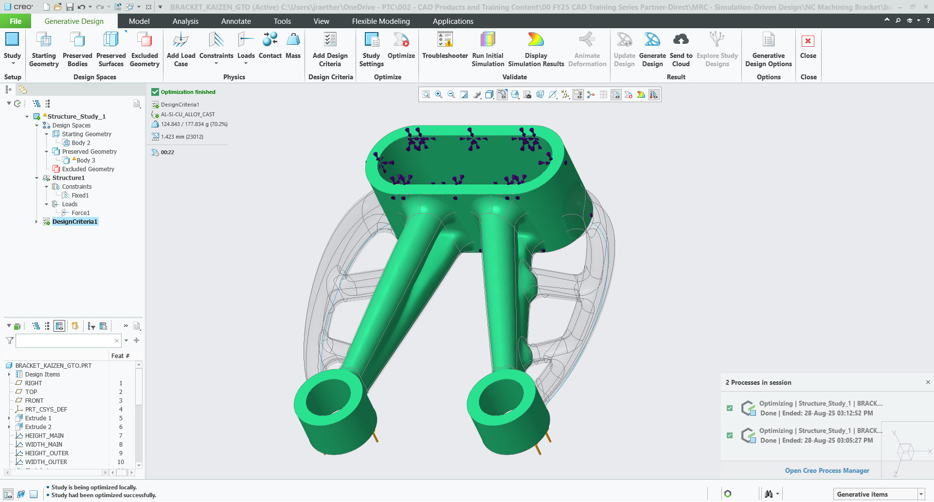
The Kaizen workflow supports the concept of continuous improvement. Simulation-driven design can also be equally useful for engineers who want to use an existing part’s geometry as the starting point for the generative process.
The key setup here is to use the “Limit Volume” constraint within GTO. The engineer can specify a target volume, for example, 70 percent of the existing part’s volume. GTO then systematically removes the least critical material. This shows which areas of the existing part contribute most to structural integrity, and what areas are less critical to the overall design. With this information, engineers can make informed decisions to enhance the quality and performance of next generation designs. Throughout the Kaizen process, engineers use CSL to evaluate design choices in pursuit of specified design goals and objectives.
As part of the SuperTruck project, Volvo used GTO to enhance an existing product, the forward engine mount, which was designed 17 years ago using cast iron and remains in production. The automotive manufacturer achieved a 75 percent weight reduction and an 82 percent decrease in peak stress.
The continuous improvement workflow has a direct impact on the company’s sustainability goals. By identifying and removing unnecessary material from existing parts, companies can reduce material costs and enhance product performance. For heavy-duty vehicles, even a slight weight reduction can lead to substantial gains in fuel efficiency.
Another option is to use CSL throughout the Kaizen workflow. The process starts using CSL to identify and document baseline measures such as stress, strain and deformation. These values serve as checkpoints when evaluating design modifications and changes throughout the Kaizen workflow. As the engineer makes changes to the design, real-time analysis reveals whether the change helped or hurt the design. Using CSL eliminates assumptions and guesswork when exploring design options and alternatives. Engineers can focus on design refinement and optimization to introduce innovation and quality into next generation designs. The final step in the process is to use Creo Ansys Simulation to perform high-fidelity analysis.
Creo adoption through MRC support
Maintenance Reseller Corporation (MRC), a long-standing PTC partner, has always been at the forefront in driving the adoption of PTC Creo. The primary role of MRC is to serve as a sales, renewal, and support channel for PTC software, including the Creo platform.
“Our focus has always been on ensuring that our customers utilize Creo to the most of their advantage, whether that’s by keeping them informed of extensions that can assist their design or optimization process, or by providing updates on each new Creo release or simulation update,” says Esthefany Hung, marketing manager at Maintenance Reseller Corporation.
Conclusion
Simulation-driven design, using PTC Creo and its extensions, provides a technique for developing products with a continuous feedback loop. This yields numerous benefits, including higher product quality, reduced development costs, faster time-to-market, and risk mitigation. In addition to this, simulation-driven workflows tend to deliver innovative solutions that drive the development of next-generation products across various industries.
It is now evident that traditional sequential workflows are no longer sufficient to maintain a competitive edge in today’s demanding market. The adoption of simulation-driven design is the next step for engineering teams.
Ready to take simulation-driven design further?
Download the free whitepaper “How Creo Supports Sustainable Product Development” to see how you can reduce costs, accelerate innovation and build more sustainable products. MRC is here to answer your questions and help you get the most out of Creo — reach out anytime.